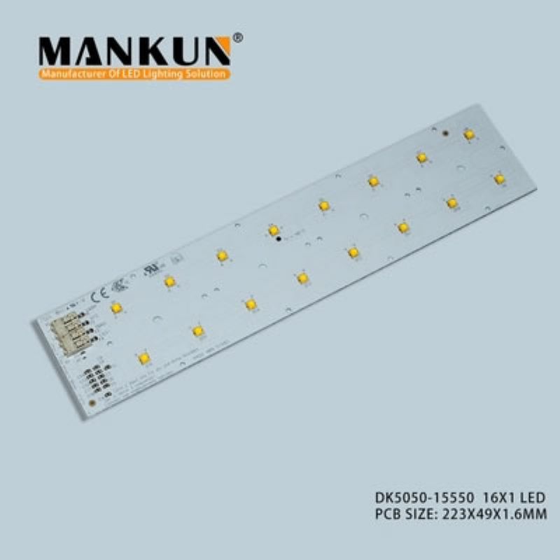
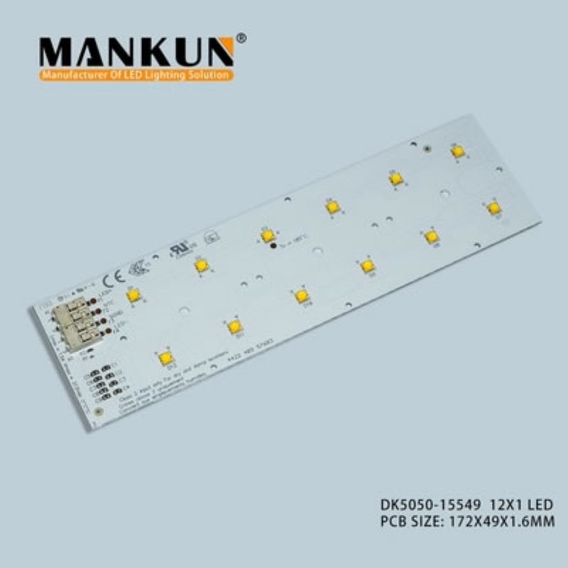
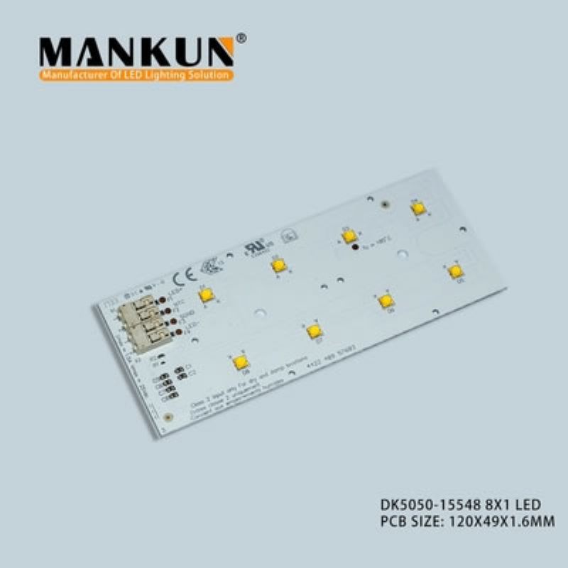
High Bright SMD3535 LED Light Circuit Board 4000K Color Temperature
序号 收款公司1 明纬(广州)电子有限公司
2 万可电子(天津)有限公司
3
Get Best Price Contact Now
|
Type: |
LED Modules |
Luminous Intensity: |
High Bright |
|
Color Rendering Index(Ra): |
80 |
Color Temperature: |
4000K |
|
Application: |
Street Lamps |
Light Source: |
3535 White SMD LED |
|
Product Name: |
Injection Led Module |
||
|
High Light: |
SMD3535 LED Light Circuit Board ,SMD3535 LED PCB Board,4000K LED Light Circuit Board |
||
High Bright SMD3535 LED Light Circuit Board 4000K Color Temperature
Zhaga Outdoor Module SMD3535 LED Street Light Lamp Pcb Led Light Module
Approval marks:
|
Technical data |
|
|
Beam characteristic |
120° |
|
Ambient temperature range |
-40 ... +80 °C |
|
tp rated |
75 °C |
|
tc |
105 °C |
|
Irated |
650 mA |
|
Imax |
1,200 mA |
|
Max. permissible LF current ripple |
1,320 mA |
|
Max. permissible peak current |
2,000 mA / max. 10 ms |
|
Max. working voltage for insulation |
370 V |
|
Max. working voltage for insulation with lens |
670 V |
|
Insulation test voltage |
1.74 kV |
|
CTI of the printed circuit board |
> 600 |
|
ESD classification |
Severity level 4 |
|
Risk group (IEC 62471) |
RG2 (Ethr = 684 lx, RG1 at d ≥ 48 cm) |
|
Classification acc. to IEC 62031 |
Built-in |
|
Type of protection |
IP00 |
|
Lumen maintenance L70B50 |
100,000 h |
|
Guarantee |
5 Year(s) |
|
Specific technical dataFilter |
||||||||||
|
Type① |
Photo-metric code |
Useful luminous flux at tp = 25 °C② |
Expected luminous flux at tp rated ③ |
Typ. forward current |
Min. forward voltage at tp = 75 °C |
Max. forward voltage at tp = 25 °C |
Typ. power con-sump-tion at tp = 75 °C ④ |
Efficacy of the module at tp = 25 °C |
Expected efficacy of the module at tp rated |
Col-our ren-der-ing in-dex CRI |
|
▼ 121*49mm - 2x4 2000lm – Operating mode NM |
||||||||||
|
AL15548 |
827/579 |
2,144 lm |
2,024 lm |
650 mA |
21.5 V |
24.0 V |
14.97 W |
143 lm/W |
139 lm/W |
> 80 |
|
830/579 |
2,354 lm |
2,224 lm |
650 mA |
21.5 V |
24.0 V |
14.97 W |
157 lm/W |
153 lm/W |
> 80 |
|
|
840/579 |
2,435 lm |
2,295 lm |
650 mA |
21.5 V |
24.0 V |
14.97 W |
163 lm/W |
158 lm/W |
> 80 |
|
|
850/579 |
2,460 lm |
2,320 lm |
650 mA |
21.5 V |
24.0 V |
14.97 W |
164 lm/W |
159 lm/W |
> 80 |
|
|
722/579 |
1,802 lm |
1,742 lm |
550 mA |
21.2 V |
23.9 V |
12.60 W |
143 lm/W |
142 lm/W |
> 70 |
|
|
730/579 |
2,124 lm |
2,054 lm |
550 mA |
21.2 V |
23.9 V |
12.57 W |
169 lm/W |
167 lm/W |
> 70 |
|
|
740/579 |
2,270 lm |
2,190 lm |
550 mA |
21.2 V |
23.9 V |
12.57 W |
181 lm/W |
180 lm/W |
> 70 |
|
|
765/579 |
2,270 lm |
2,190 lm |
550 mA |
21.2 V |
23.9 V |
12.60 W |
181 lm/W |
179 lm/W |
> 70 |
|
|
▼ 223*49mm - 2x8 4000lm – Operating mode NM |
||||||||||
|
AL15550 |
827/579 |
4,288 lm |
4,038 lm |
650 mA |
43.1 V |
48.0 V |
29.93 W |
143 lm/W |
139 lm/W |
> 80 |
|
830/579 |
4,708 lm |
4,438 lm |
650 mA |
43.1 V |
48.0 V |
29.93 W |
157 lm/W |
153 lm/W |
> 80 |
|
|
840/579 |
4,871 lm |
4,591 lm |
650 mA |
43.1 V |
48.0 V |
29.93 W |
163 lm/W |
158 lm/W |
> 80 |
|
|
850/579 |
4,919 lm |
4,639 lm |
650 mA |
43.1 V |
48.0 V |
29.93 W |
164 lm/W |
159 lm/W |
> 80 |
|
|
722/579 |
3,605 lm |
3,465 lm |
550 mA |
42.7 V |
47.6 V |
25.10 W |
143 lm/W |
141 lm/W |
> 70 |
|
|
730/579 |
4,248 lm |
4,088 lm |
550 mA |
42.7 V |
47.6 V |
25.13 W |
169 lm/W |
167 lm/W |
> 70 |
|
|
740/579 |
4,540 lm |
4,379 lm |
550 mA |
42.7 V |
47.6 V |
25.13 W |
181 lm/W |
179 lm/W |
> 70 |
|
|
757/579 |
4,540 lm |
4,379 lm |
550 mA |
42.7 V |
47.6 V |
25.13 W |
181 lm/W |
179 lm/W |
> 70 |
|
|
765/579 |
4,447 lm |
4,250 lm |
550 mA |
42.7 V |
47.6 V |
25.13 W |
177 lm/W |
174 lm/W |
> 70 |
|
|
①HE ... High Efficiency, NM ... Nominal Mode, HO ... High Output. |
||||||||||
|
②Tolerance of useful light flux - 0 % / + 15 %. Measurement uncertainty ± 10 %. |
||||||||||
|
③Tolerance of expected light flux - 0 % / + 15 %. Measurement uncertainty ± 10 %. Based on calculation. |
||||||||||
|
④Tolerance of power consumption Pon ± 10 %. Measurement uncertainty ± 5 %. |
||||||||||
Waveform Lighting's LED modules operate on DC 24V. To connect these to mains power from a wall outlet (e.g. AC 120V), you will need additional accessories to ensure electrical compatibility.
Electrical connections are made via WAGO 2060 terminal blocks located on both ends of the module. These terminal blocks accept solid or stranded wire with 18-24 AWG thickness. Most DC power supplies utilize DC barrel jacks, which are not directly compatible with these terminal blocks. We recommend using a DC jack-to-wire adapter.
Below are the accessories needed, along with links to our product pages where you can purchase everything you need from our store.
1) DC 24V constant voltage power supply with sufficient power capacity.
(Link: FilmGrade 24V DC Power Supply, sufficient for 14 modules of ABSOLUTE SERIES Linear Module, maximum 10 modules per daisy-chain)
-----------------------------
If using FilmGrade 24V DC Power Supply or similar power supply with DC barrel jack, you will need an adapter. See below for two options: 2A or 2B.
2A) Female DC jack-to-wire (pigtail) adapter
(Link: Female DC Barrel Jack to Pigtail Wire Cable, wire ends need to be stripped 0.28-0.35 in (7-9 mm) for best fit into WAGO 2060 terminal block receptacle)
OR
2B) Female DC jack plug adapter + 18-24 AWG wire
(Link: Female DC Barrel Jack Plug Adapter, wire ends need to be stripped 0.28-0.35 in (7-9 mm) for best fit into WAGO 2060 terminal block receptacle)
-----------------------------
3) Clamp release tool (or screwdriver) for WAGO 2060 terminal block to insert and release wires from WAGO 2060 terminal block.
Small-head philips/flathead screwdrivers can be used instead, but is not recommended as it can cause damage to the terminal block.
(Link: WAGO 206-860 Clamp Release Actuator Tool)
4) For mounting, M3 screws or thermally resistant double-sided tape
5) [OPTIONAL] For daisy-chaining, if connecting more than 1 module: 18-24 AWG wire or WAGO 2060-901 Board-to-Board Link.
WAGO 2060-901 is best suited for a gap-less extension of multiple modules, but does not allow for any change of direction.
(Link: WAGO 2060-901 Board-to-Board Link)

Need additional technical help? Contact us at hello@waveformlighting.com
Step 1: Find the wire-end of the DC power input (pigtail connector cable or wire leads from power supply), and strip the insulation approximately 0.28-0.35 in (7-9 mm).

Step 2: While pressing down on the terminal block clamp using the dedicated clamp release tool (recommended) or a screwdriver, insert the open wire into the receptacle. Each terminal block is marked (+) and (-); these need to match the polarity of the power cable, typically marked red (+) and black (-).
Step 3: Repeat the same for the other wire. You may need to split the red and black wires further if their insulation jackets are joined.
Step 5: Gently tug on the wires to ensure that the wires have been securely inserted and clamped.

Step 6: Plug the DC power plug in. The module should now illuminate. Ensure that the input power is 24V DC and that the polarity is correct. Insufficient voltage will result in no or low illumination, while exceeding 24V DC may result in damage to the LEDs.
Applications
• Road lighting
• Urban street lighting
• Flood and Area lighting
• Tunnel lighting
• High bay lighting
Key features and benefits
• Enables OEM optical differentiation with lenses from third party portfolios matching every project’s needs
• High module efficiency for fixture performance
• Best in class reliability testing for OEM peace of mind
• Wide operating thermal range
• Temperature and driving current designed for fixture optimization
• Patented module surge protection
• Optical flexibility via third party lenses
• Instant full light
• Flexible lumen output
| PCB | 1.2 | 300 |
| LED | 32 | 4 |
| SMD | ||
| 端子 | 4 | 1 |
| SMD | ||
| IC | 1 | |
| 包装 | ||


